
I SPI With My Hacking Eye
SPI Flash for Bug Bounty Hunters
| What is SPI Flash?
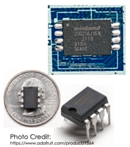
SPI is an acronym that stands for Serial Peripheral Interface, which is a synchronous serial communication protocol used in embedded systems for communication over very short distances. A key advantage of using SPI in embedded systems is it typically requires only 4 wires (VCC, GND, Data-In, Data-Out). Some more advanced implementations use Dual-SPI or Quad-SPI, which requires more wires. SPI Flash is a solid-state memory chip, typically in a very small form factor, which uses the SPI protocol to communicate with the embedded system processor. In most use cases, SPI flash will be soldered directly onto the device circuit board (PCB) and serves an integral role in the device’s operation. |
 |
Common Uses for SPI Flash
While the uses for SPI flash are as varied as the devices in which we find it, there are a handful of common use cases that we’ll encounter as bug bounty hunters. These include:
- Sole memory for small footprint devices with minimal storage requirements (e.g. IoT). In these cases, code may be executed in place (directly from the SPI Flash) or loaded to RAM and executed from there.
- Bootloader ROM for more complex hardware devices (e.g. routers, WiFi access points, etc.).
- BIOS/Firmware storage in modern desktop, laptop, and server computers.
- Firmware storage for integrated controllers in modern PCs (e.g. RAID controllers, video cards, etc.).
 |
Physical Disassembly Tools
As a bug bounty hunter, the first step in gaining access to SPI flash is physical disassembly of the device case/chassis. This step can be difficult and prone to damage the device if done without the right tools for the job. Anyone who’s tried to crack open the plastic case on a router can attest to that. I recommend a kit, such as the one depicted here, which includes a few essential disassembly tools:
|
| Extracting SPI Flash Chip
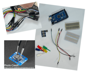
Once we’ve gained access to the device circuit board, our next task is to remove the SPI Flash chip from the board and read its contents. For this, we’ll need some more basic electronics tools, including:
|
 |
Overview
At a high level, the process that we’ll follow for extracting the SPI Flash contents is broken down into four (4) steps:
- Step 1: Recon
- Step 2: Removing the SPI Flash chip
- Step 3: Reading the SPI Flash contents
- Step 4: Making sense of the extracted SPI Flash contents
Step 1: Recon
Before removing the SPI Flash chip to read its contents, we’ll first want to do a little recon and research. Start by reviewing all the chips on the device circuit board to identify all chips with eight (8) pins/legs. Write down the part number from each 8-legged chip and use your favorite search engine to locate the chip’s datasheet. This will help us identify which chips are SPI Flash and which are some other type of chip. We’ll also need to reference the datasheets in the next step, so keep them handy.
Step 2: Removing the SPI Flash Chip
To remove the SPI Flash chip from the device circuit board, we have a couple different options. The first is to use a solder gun to heat each leg of the SPI Flash one-by-one as you gently lift the leg from the solder pad using tweezers. This approach can be tedious and prone to damage the SPI Flash legs, so be sure to take your time and be patient. A second option is to use a heat gun to blow hot air over the SPI Flash pins while gently lifting on the body of the flash chip. This approach has the advantage of hitting all the pins on each side of the flash chip at once and is less likely to result in damaging the flash chip.
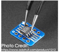
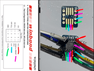
Next, you’ll want to solder the SPI Flash chip to an SOIC-8 breakout board so it’s easier to connect the Arduino to the SPI Flash pins. The below picture demonstrates placing the flash chip on the SOIC-8 breakout board.
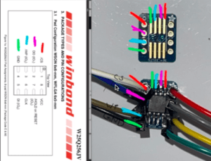
Before proceeding to the next step, we’ll also need to map the SOIC-8 pins to their functions, as indicated by the SPI Flash datasheet. The typical pin out looks like this:
 |
 |
Step 3: Reading the SPI Flash Contents
While there are plenty of plug-and-play commercial products available for reading SPI Flash contents, we can also use inexpensive tools that you might already have on-hand. Namely, an Arduino, breadboard, and jumper wires.
The first step is to wire the SPI Flash chip to our Arduino. In this example, the SPI Flash chip operates a 3V. It’s very important to review the datasheet to determine the voltage at which the SPI Flash operates. If you attach a 3V SPI Flash chip to the 5V pin on the Arduino, there’s a very good chance it’ll destroy the flash chip.
The typical pin out mapping is:
| Arduino Pin | to | SPI Flash Pin |
| 10 | <-> | 1 (chip select) |
| 12 | <-> | 2 (data out) |
| 3V | <-> | 3 (write project) |
| GND | <-> | 4 (ground) |
| 11 | <-> | 5 (data in) |
| 13 | <-> | 6 (clock) |
| 3V | <-> | 7 (hold/reset) |
| 3V | <-> | 8 (vcc+) |
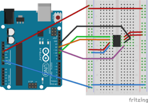
Image Credit:
http://www.jk-quantized.com/blog/2015/05/07/arduino-to-flash-bios
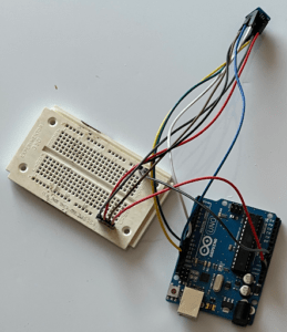
Here’s what my demo setup looks like:
Now that we have the SPI Flash chip physically wired to the Arduino, it’s time to program the Arduino to read the SPI Flash contents. For this, we can use the below source code, which is also available at https://github.com/nerdwell/LevelUpX-SPI-Flash-Demo.
| #include <SPI.h>
/* /* /* /* // We’ll send each byte read from the flash over to the computer via the Arduino serial port, so we must initialize serial communications. // We set the pin mode for each pin that we’ll use to commmunicate with the SPI flash chip. // Set the CS pin to high, which pauses the SPI chip while we get some other stuff ready. // Now we’ll tell the Arduino SPI library that we’re about to begin SPI communications. void loop() /* digitalWrite(SLAVESELECT, LOW); /* /* // Now we increment the address to read the next byte from the SPI flash chip. /* delay( 60000 ); } |
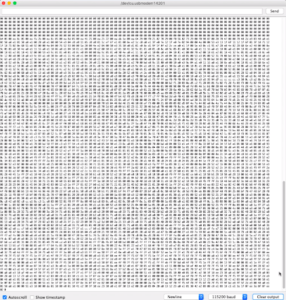
When we load this to the Arduino (using the Arduino desktop app), it’ll dump the SPI Flash contents to the “serial monitor” in the Arduino desktop app, as depicted below:
Step 4: Making Sense of the SPI Flash Contents
The last step in our adventure is to actually make sense of the extracted SPI Flash contents, which can sometimes be the trickiest part. To begin, just copy the contents of the Arduino serial monitor and paste into a new file. Then, open with a hex editor to see if any common file headers jump out (e.g. ELF file header).
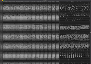
If you don’t immediately recognize any file headers, there are a few handy tools that can help identify the file contents:
- Binwalk firmware analysis tool.
- Linux/MacOS “file“ command.
- Linux/MacOS “xxd” tool.
Conclusion
The uses for SPI Flash are as diverse as the devices containing these chips. By learning how to dump and interpret SPI Flash contents, we can greatly enhance our insight into the inner workings of hardware hacking targets. While there are commercial products that simplify dumping SPI Flash contents, creative hackers can accomplish the same thing using an inexpensive kit, as we demonstrated today. These techniques are also great for bug bounty hunters just getting started into hardware hacking, as it helps to lower the barriers to entry.
From the bug bounty hunter’s perspective, SPI Flash can provide us with executable code for reverse engineering, cryptographic keys, and even hardcoded API keys for backend cloud services. Once the SPI Flash contents have been dumped, use the “binwalk,” “file,” and “xxd” command line tools to identify and extract file format information about the flash contents. Then, use your favorite decompiler to reverse engineer the executable code; or use the “strings” command line tool to search for hardcoded keys.
About the Author
Nerdwell is a systems and security engineer with a passion for bug bounty and vulnerability research. He currently works in critical infrastructure protection and has experience supporting technology in a variety of industries, ranging from manufacturing to healthcare. With over 20 years’ experiences, Nerdwell understands firsthand the challenges of building and supporting complex technology solutions securely. In addition to finding bugs and performing security research, Nerdwell enjoys networking and sharing knowledge with fellow hackers.
Get Started with Bugcrowd
Every minute that goes by, your unknown vulnerabilities leave you more exposed to cyber attacks.


